The GIGABYTE MZ72-HB0 (Rev 3.0) Motherboard Review: Dual Socket 3rd Gen EPYC
by Gavin Bonshor on August 2, 2021 9:30 AM EST- Posted in
- Motherboards
- AMD
- Gigabyte
- GIGABYTE Server
- Milan
- EPYC 7003
- MZ720-HB0
Visual Inspection
From a design standpoint, the MZ72-HB0 has a typical blue GIGABYTE Server PCB, with blue memory slots, creamy white connectors, and black PCIe slots with metal slot reinforcement. Even though this is a board designed for use in a server chassis, it has an E-ATX sized frame and could be mounted into a regular chassis if a user wishes to do so. The PCB itself is littered with connectivity, including various headers, power connectors, and controllers, with practically all of the PCB playing a vital role in the board's operation. Due to the board's function over style ethos, there are no flashy RGB LEDs or such here.
Dominating the top half of the board are two SP3 sockets with support for AMD's 3rd generation EPYC Milan processors. Each SP3 socket can accommodate up to 280 W processors per socket, including the top SKU, the AMD EPYC 7763 ($7890). Due to it being a dual-socket motherboard, it doesn't support the P-series EPYC processors which are designed for single-socket motherboards only. It's also worth noting that there are two revisions of this model, the Rev 1.x which supports just EPYC 7001 (Naples) and 7002 (Rome) processors, and the one we have on test, the Rev 3.0 which supports the EPYC 7002 (Rome) and latest EPYC 7003 (Milan) processors.
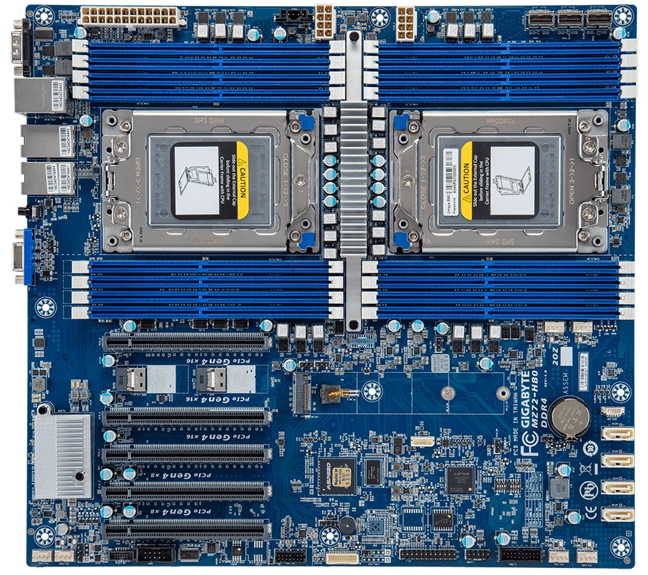
Flanking each of the SP3 sockets is are eight memory slots, with sixteen memory slots in total with two EPYC processors installed. The MZ72-HB0 supports various types of memory, including RDIMM and LDRIMM up to 128 GB per module, with support for 3DS LRDIMM/RDIMM memory of up to 256 GB per module. This means users can install a maximum of 2 TB of system memory, with memory operating in eight-channel with all of the slots populated. GIGABYTE includes support for up to DDR4-3200.
Focusing on the lower portion of the board, GIGABYTE includes five full-length PCIe 4.0 slots, with the top three operating at PCIe 4.0 x16, and the bottom two operating at PCIe 4.0 x8. Given that this is a dual-socket motherboard, each of the CPUs control different slots in the following configuration:
- Slot_6 - PCIe 4.0 x16 (CPU 0) - Top slot
- Slot_4 - PCIe 4.0 x16 (CPU 0)
- Slot_3 - PCIe 4.0 x16 (CPU 1)
- Slot_2 - PCIe 4.0 x8 (CPU 0)
- Slot_1 - PCIe 4.0 x8 (CPI 1) - Bottom slot

For cooling, GIGABYTE includes a total of six 4-pin headers, with two for CPU fans, and four for chassis fans. The two CPU fans are located by the right-hand CPU socket, whereas the rest can be found along the bottom of the PCB.

Sandwiched in-between the top two full-length PCIe slots (Slot_6/Slot_4), are two PCIe 4.0 x4 SlimSAS headers, This allows for more NVMe based storage options to be used, which is commonplace in the data center.
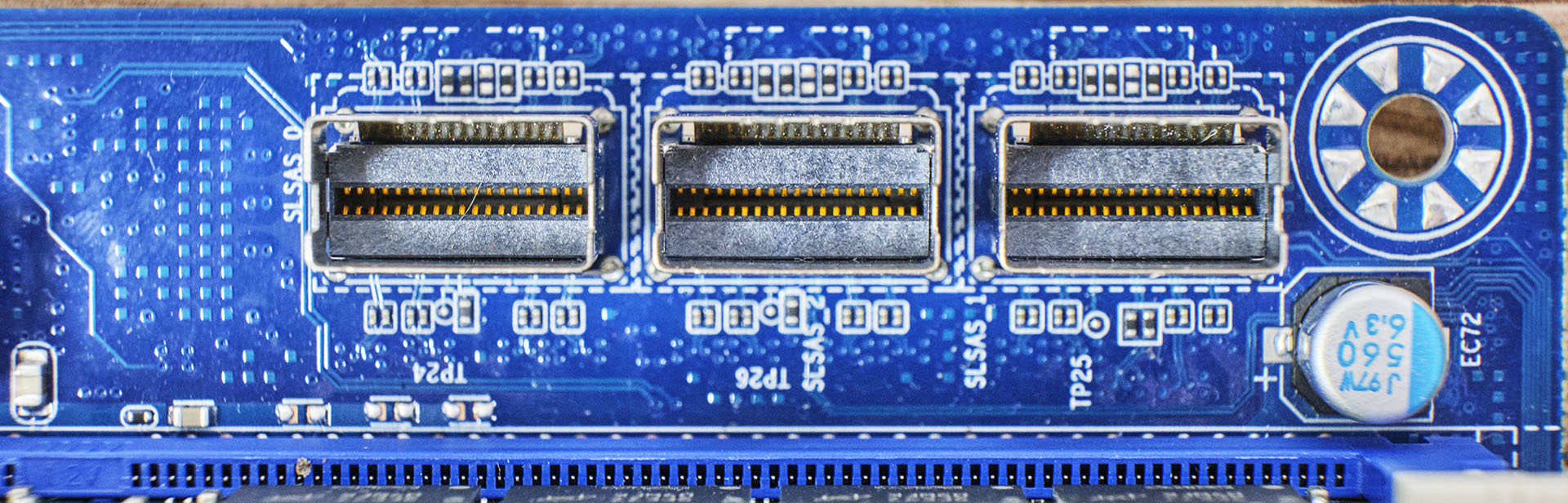
Other storage options on the GIGABYTE MZ72-HB0 include three SlimSAS ports, with each port allowing for four SATA ports (twelve in total), or users can use each slot for additional NVMe capable PCIe 4.0 x4 storage. For users looking to install single drives, GIGABYTE includes four 7-pin SATA slots.
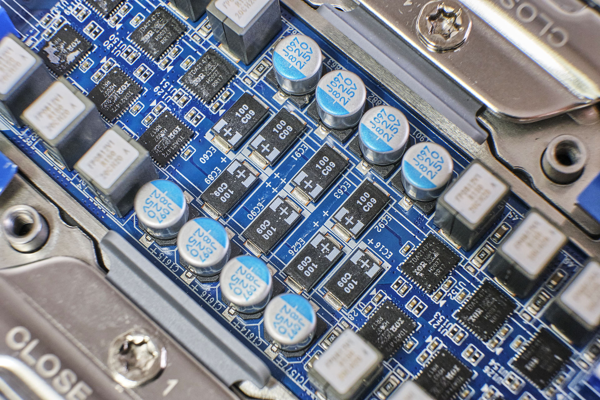
The power delivery on the MZ72-HB0 is quite intricate and complicated, which is often the case on monstrous dual-socket motherboards. Starting with the CPU VCore, each socket has its own independent power delivery with six Infineon TDA21472 power stages and is driven by an International Rectifier IR35201 PWM controller. This means that each SP3 socket has a 6+0 phase power delivery.
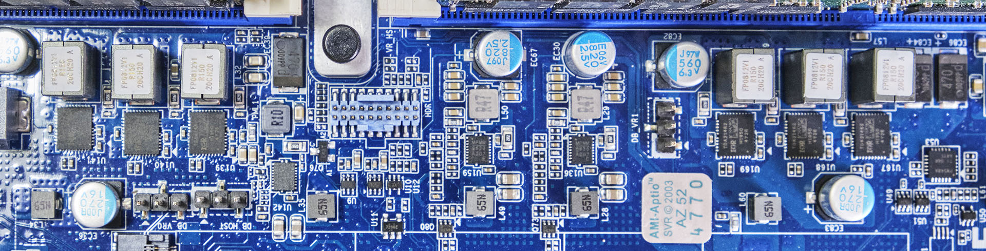
Looking at the memory section of the power delivery, GIGABYTE is using six Infineon TDA21462 60 A power stages in two groups of three for each set of eight memory slots. It is controlled using an International Rectifier IR3584 PWM controller, with two sets of these operating independently. For the VSoC section, GIGABYTE is using two Infineon TDA21462 60 A power stages and is controlled by a single International Rectifier IR35204 PWM controller. Again, there are two sets of these with one for each installed processor.
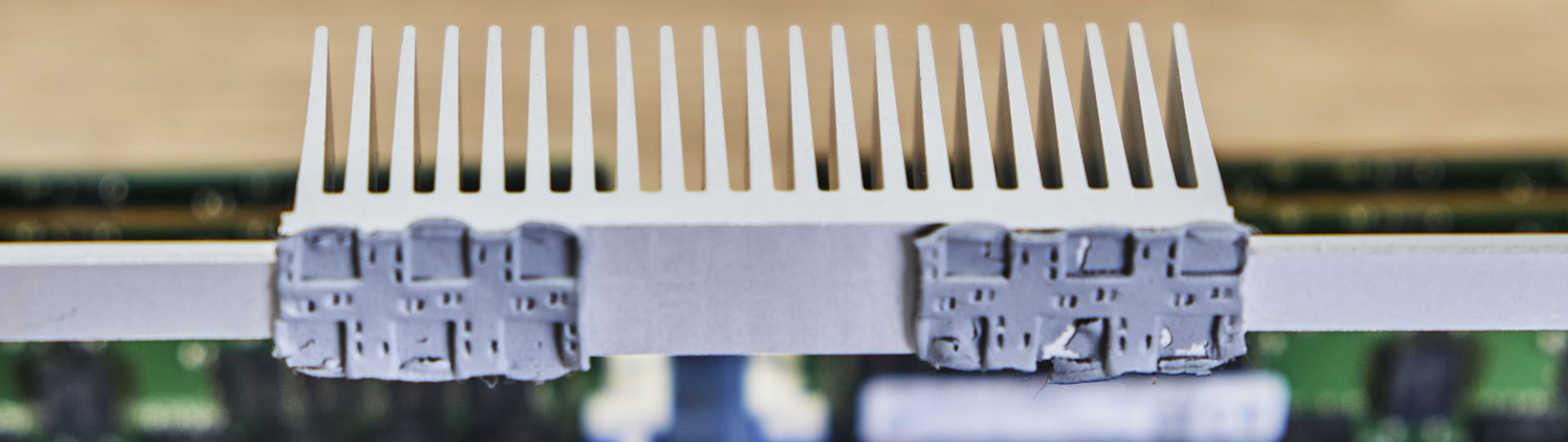
Keeping the CPU section of the power delivery cool is an aluminum heatsink with a long strip which is held into place with two black plastic clasps with springs. The main bulk of the cooling properties which sit directly over the power stages is a large finned section, which is designed to use airflow to dissipate the heat effectively - anyone using this board has to make sure there is lots of airflow, as if the board is in a server in a datacenter. The memory and VSoC areas of the power delivery don't include heatsinks, and instead, rely heavily on the airflow.
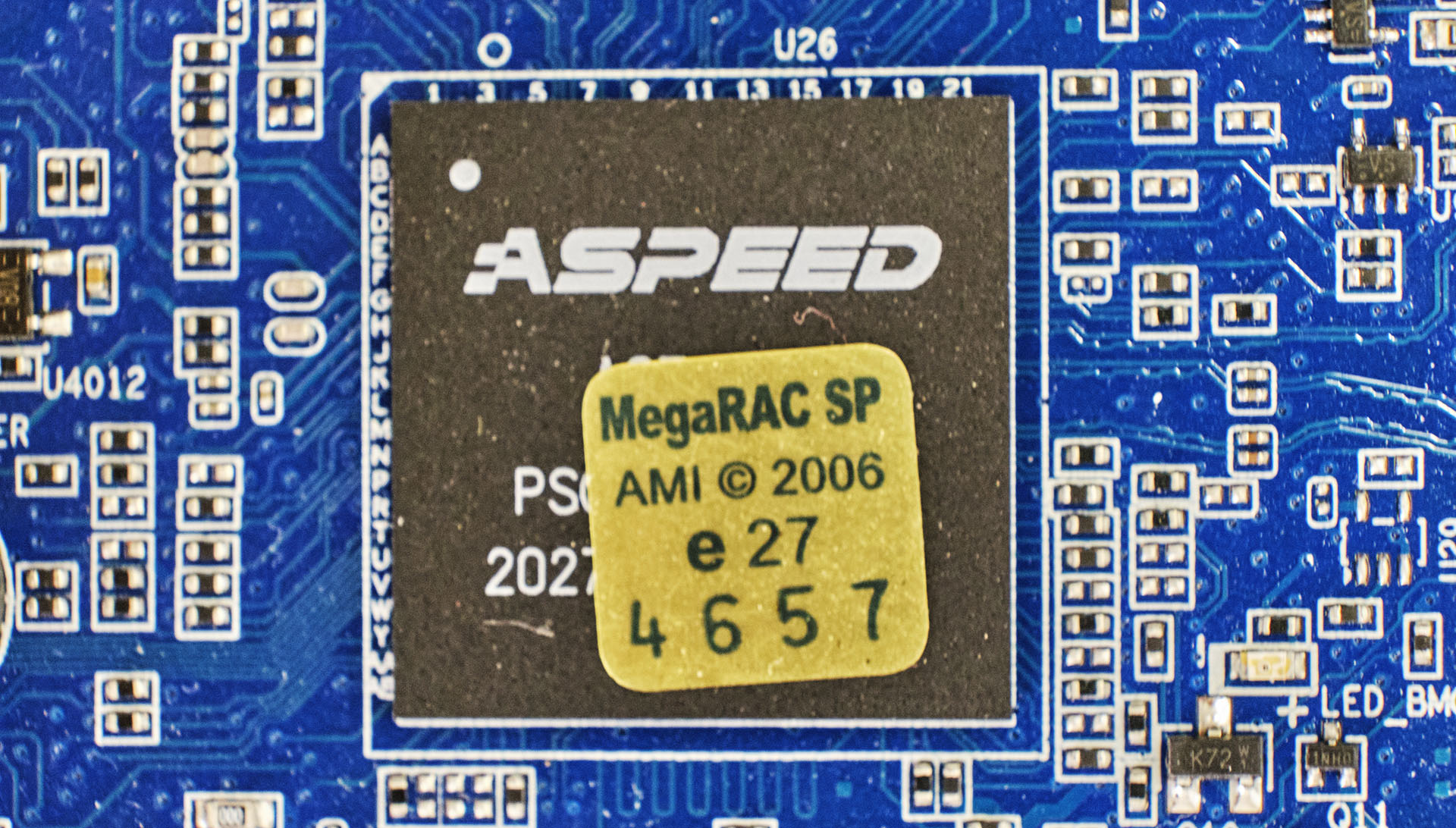
GIGABYTE's baseboard management controller (BMC) of choice is the ASPEED AST2600. This allows board management functionality including both over JAVA and HTML5 formats, as well as LDAP/AD/RADIUS support, and access to GIGABYTE's AMI MegaRAC SP-X browser-based interface.
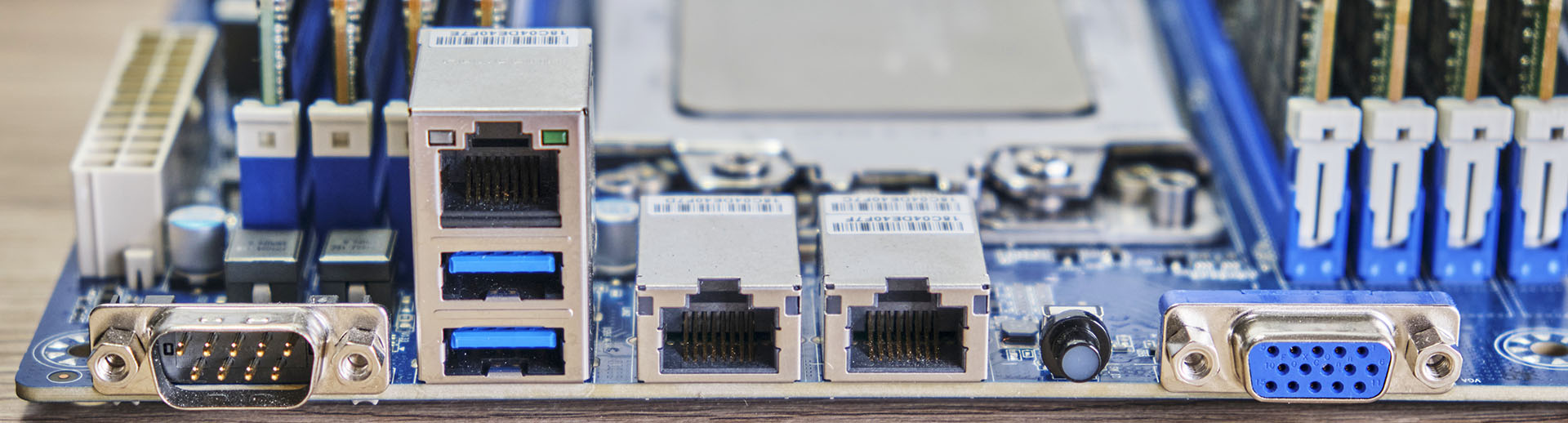
On the rear panel is a basic, yet functional set of input and output. In terms of USB, there are just two USB 3.0 Type-A ports, with front panel headers offering for more expansion; one USB 3.1 G1 Type-A header offering two Type-A ports, and one USB 2.0 header, also offering two additional Type-A ports. Networking is premium, with one Realtek RTS5411E Gigabit management port offering access to the BMC, with two 10 GbE BASE-T ports powered by a Broadcom BCM57416 Ethernet controller. Also on the rear panel is a D-Sub, which allows users to connect to the board's ASPEED BMC controller, a serial COM port, and an ID button with a built-in LED.


28 Comments
View All Comments
Grayswean - Monday, August 2, 2021 - link
256 threads, 1024 bits of memory bus -- resembles a low-end GPU of ~5 years ago.Oxford Guy - Tuesday, August 3, 2021 - link
What ‘low-end’ GPUs came with more than a 128-bit memory bus?bananaforscale - Friday, August 6, 2021 - link
You need HBM to go past 1024 bits, or compute cards. Low end is 64 to 128 bit bandwidth, and consumer cards don't hit 1024.Oxford Guy - Sunday, August 15, 2021 - link
Consumer cards did ship with HBM, in 4096-bit (Fury-X) and 2048-bit (AMD’s HBM-2 cards) as I recall. However, none of those were priced for the low end.Threska - Monday, August 2, 2021 - link
"In terms of power, we measured a peak power draw at full load with dual 280 W processors of 782 W."Looks like a new PSU is in order. Add in things like a GPU might push things over the edge.
Threska - Monday, August 2, 2021 - link
" It does include a TPM 2.0 header for users wishing to run the Windows 11 operating system, but users will need to purchase an additional module to use this function as it doesn't come included in the packaging."I assume Windows 11 doesn't use any on-chip TPM.
https://semiaccurate.com/2017/06/22/amds-epyc-majo...
Mikewind Dale - Monday, August 2, 2021 - link
Why did you measure long idle differently? I agree it's interesting to measure power consumption while turned off. But why conflate that measurement with other systems that are turned on with idling OSes?And that DPC latency looks terrible. I see several other EPYC systems in the chart that don't have anywhere near that bad latency. In fact, the lowest latency in the chart is achieved by an ASRock EPYC.
watersb - Monday, August 2, 2021 - link
2 x $7500 = $15,000 for two EPYC processors16 x $3600 = $57,600 for 4TB RAM
$1000 each for power supply, motherboard
Throw in an EATX chassis I have lying around
$75,000 before sales tax or storage.
I'd have to run a dedicated 15-Amp circuit to my main breaker box, well within a 1500 Watt spec for a standard residential receptacle.
Probably want to upgrade the UPS.
$100k ought to do it.
Mikewind Dale - Tuesday, August 3, 2021 - link
Just run a 20 amp circuit. Most of the cost is labor anyway, not the wire. The difference between the cost of a 15A wire and a 20A wire is trivial.jhh - Tuesday, August 3, 2021 - link
A 15A 120V circuit will not do it in the US, as continuous loading of that circuit only supports 1440W of continuous service. 15A x 120V x 80% derating for continuous service is 1440W. On top of that, if the UPS is recharging after a power outage, that power diverted to the battery has to come out of the circuit as well. Perhaps a 240V 15A circuit would work better. Otherwise, you would need one of those strange 20A plugs to use the sideways position in a 20A receptacle.